How to Choose the Right GPIO Pin for I2C, SPI or UART
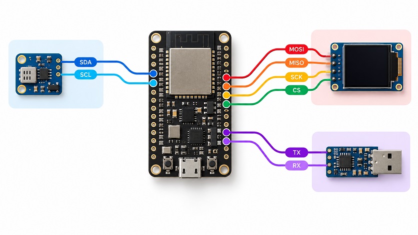
A microcontroller board may have dozens of GPIO pins, but that does not mean every pin is equally suitable for every job. This becomes especially important when connecting devices that use I2C, SPI or UART. You may...
A microcontroller board may have dozens of GPIO pins, but that does not mean every pin is equally suitable for every job.
This becomes especially important when connecting devices that use I2C, SPI or UART.
You may see an example project using GPIO21 and GPIO22 for I2C on an ESP32, while another project uses completely different pins. On an Arduino Uno, however, trying to move I2C to arbitrary digital pins will not work with the hardware I2C peripheral.
So how do you know which GPIO pins you should actually use?
The answer depends on how the microcontroller routes its internal peripherals to its physical pins.
Some boards have nearly fixed communication pins. Others provide several alternate pin mappings. Chips such as the ESP32 go even further and can route many peripheral signals through an internal GPIO matrix.
This guide explains how to choose suitable GPIO pins for I2C, SPI and UART, and what you should check before wiring your circuit.
GPIO Does Not Automatically Mean I2C, SPI or UART
GPIO stands for General-Purpose Input/Output.
A GPIO pin can normally be controlled directly by software as a digital input or output. Communication peripherals are different.
An MCU contains dedicated hardware blocks such as:
| Peripheral | Typical Signals |
|---|---|
| I2C | SDA, SCL |
| SPI | MOSI, MISO, SCK, CS |
| UART | TX, RX |
| Hardware flow-control UART | TX, RX, RTS, CTS |
For a hardware peripheral to use a pin, there needs to be an internal connection between that peripheral and the GPIO.
How that connection works varies considerably between microcontrollers.
This is why looking at the GPIO number alone is not enough.
Three Common Types of Pin Routing
You will generally encounter three approaches when choosing communication pins.
Fixed Peripheral Pins
Older and simpler microcontrollers often have communication peripherals tied to specific pins.
The ATmega328P used by the Arduino Uno is a good example.
On the Uno R3, hardware I2C uses:
| Signal | Arduino Pin |
|---|---|
| SDA | A4 / D18 |
| SCL | A5 / D19 |
Hardware SPI uses:
| Signal | Arduino Pin |
|---|---|
| SS | D10 |
| MOSI | D11 |
| MISO | D12 |
| SCK | D13 |
And the primary hardware UART uses:
| Signal | Arduino Pin |
|---|---|
| RX | D0 |
| TX | D1 |
These connections originate from the peripheral functions of the ATmega328P and are reflected directly in Arduino's official pinout.
You can emulate some protocols on other pins in software, but that is different from moving the actual hardware peripheral.
Alternate-Function Pins
Many modern microcontrollers allow a peripheral to appear on several predefined pins.
STM32 devices are a common example.
An STM32 GPIO can operate as ordinary GPIO, analog I/O, or an alternate function. The alternate-function multiplexer connects selected peripherals such as I2C, SPI or UART to particular pins. A single pin can have multiple possible alternate functions, but the available combinations are defined by the specific STM32 device.
For example, USART1 TX might be available on more than one pin, but that does not mean USART1 TX can be placed on every GPIO.
You therefore need to check the MCU's alternate-function table.
The Raspberry Pi RP2040 used on the original Pico follows a similar concept.
Each GPIO has a predefined function-select table. For example, GPIO0 can provide SPI0 RX, UART0 TX or I2C0 SDA, among several other functions. GPIO1 can provide SPI0 CS, UART0 RX or I2C0 SCL. Other GPIOs have different combinations.
This gives you flexibility, but only within the combinations supported by the silicon.
GPIO Matrix Routing
ESP32-family chips are considerably more flexible.
On the original ESP32, peripheral input and output signals can be routed through the GPIO matrix, allowing many internal peripheral signals to connect to different GPIO pins. Espressif describes this as a highly configurable I/O architecture.
That is why ESP32 Arduino examples often allow code such as specifying custom SDA and SCL pins when starting the I2C interface.
But this flexibility does not mean that every GPIO is automatically a good choice.
Some GPIOs may be strapping pins, connected to flash or PSRAM, input-only, used by USB, or otherwise restricted.
The question should therefore not be:
"Can this peripheral be routed to this GPIO?"
It should be:
"Can it be routed there safely without interfering with anything else?"
Choosing GPIO Pins for I2C
I2C normally requires two signals:
SDA carries data, while SCL carries the clock.
If the board has clearly marked SDA and SCL pins, those are usually the best starting point.
On a board with fixed I2C pins, use those pins unless you deliberately intend to implement software I2C.
On a microcontroller with alternate-function routing, check which GPIO pairs support the I2C peripheral you intend to use.
On highly flexible devices such as many ESP32 variants, you may be able to select different GPIOs in software.
There is another important electrical consideration with I2C: SDA and SCL are open-drain signals and require pull-up resistors.
Many breakout boards already include pull-ups. Others do not.
The pull-ups also determine the logic voltage of the bus. A sensor board whose SDA and SCL lines are pulled up to 5 V can therefore be a problem when connected to a microcontroller whose GPIOs are not 5 V tolerant.
Pin selection is not just a software-routing problem. You also need to check the electrical characteristics of the pins.
Avoid Pins That Affect Boot
Be particularly careful when assigning I2C to boot or strapping pins.
ESP32 devices, for example, sample certain GPIO states during reset to determine boot configuration. Espressif specifically warns designers to consider the state of strapping pins during power-up.
An I2C pull-up may hold such a pin high during reset.
Depending on the chip and GPIO, that can affect startup behavior.
If you have unused unrestricted GPIOs available, they are normally preferable.
Choosing GPIO Pins for SPI
SPI generally requires more signals than I2C.
A typical SPI connection uses:
| Signal | Function |
|---|---|
| SCK | Serial clock |
| MOSI | Controller-to-peripheral data |
| MISO | Peripheral-to-controller data |
| CS | Chip select |
SPI is often more sensitive to pin selection because it can operate at much higher speeds than I2C.
On microcontrollers with dedicated SPI pin mappings, using the native SPI pins is generally the simplest choice.
On flexible devices, you may be able to move the SPI signals elsewhere, but there can be a performance cost.
For example, the ESP32 can route SPI signals through its GPIO matrix instead of using the peripheral's dedicated IO_MUX pins. Espressif notes that GPIO-matrix routing adds input delay, which can reduce the maximum reliable SPI speed. For high-speed SPI, Espressif recommends using the dedicated IO_MUX pins.
This distinction may not matter for a slow sensor.
It can matter significantly for devices such as displays, SD cards and high-speed ADCs.
Chip Select Is Often the Most Flexible Signal
The CS signal deserves separate consideration.
SPI uses SCK, MOSI and MISO as a shared bus. Each peripheral normally gets its own chip-select signal.
In many implementations, CS can simply be controlled as an ordinary GPIO.
This means you may need the hardware peripheral's supported pins for SCK, MOSI and MISO while still having considerable freedom when choosing CS.
Check the board and software library, though, because some hardware-controlled SPI modes impose additional requirements.
Choosing GPIO Pins for UART
A basic UART connection needs:
| Signal | Connects To |
|---|---|
| MCU TX | Device RX |
| MCU RX | Device TX |
One of the most common wiring mistakes is connecting TX to TX and RX to RX.
UART connections normally cross:
TX ? RX
RX ? TX
Pin routing then depends on the microcontroller.
On an Arduino Uno, D0 and D1 are connected to the ATmega328P's hardware UART. These pins are also involved in the board's USB serial interface, so connecting another UART device there can interfere with uploading code or communicating with the computer.
More capable MCUs often contain multiple UART peripherals and several possible pin mappings.
For example, an STM32 may provide USART1, USART2 and USART3, with each peripheral available on certain alternate-function pins. The exact mapping must be checked in that STM32 model's datasheet.
The RP2040 also allows its UART peripherals on several predefined GPIO combinations rather than arbitrary pins.
On ESP32-class devices, UART routing is usually much more flexible because signals can use the GPIO matrix.
Check Whether the Pin Is Already Being Used
A GPIO may technically support your communication peripheral but already have another job on the board.
Examples include:
| Existing Function | Possible Problem |
|---|---|
| Built-in LED | External device may toggle the LED |
| BOOT button | External circuitry may affect startup |
| USB D+ / D? | Can interfere with native USB |
| Flash / PSRAM | May cause crashes or prevent booting |
| Debug interface | Can interfere with SWD/JTAG |
| Serial console | Can interfere with logging or programming |
| Crystal-related pin | Usually unavailable as normal GPIO |
This is especially important with compact development boards.
The microcontroller package may have many GPIOs, but the development board may internally consume several of them.
Always check the board pinout, not just the microcontroller datasheet.
Watch for Strapping and Boot Pins
A pin can work perfectly after the MCU starts running and still be a poor choice because of what happens during reset.
Boot-strapping pins are sampled during startup.
External circuitry attached to them can therefore affect how the microcontroller boots.
An LED, sensor output, pull-up resistor or pull-down resistor may force the GPIO to a state the MCU was not expecting.
This problem is common enough on ESP32 boards that strapping pins should always be checked before choosing GPIOs for permanently connected peripherals.
A pin marked as a strapping or boot-related pin is not necessarily unusable.
It simply requires more care.
If another unrestricted GPIO is available, that is usually the safer choice.
Check Input-Only and Output Restrictions
Some GPIOs cannot perform every type of signal.
A UART TX pin must be capable of output.
SPI SCK and MOSI normally require outputs when the MCU is the controller.
I2C pins need both input and output behavior because devices release the bus and monitor its state.
This means an input-only GPIO cannot simply be substituted for every communication signal.
The original ESP32 is a useful example because GPIO34 through GPIO39 are input-only. They therefore cannot serve as ordinary output signals such as SPI clocks or UART TX.
A pinout database that records direction and capability restrictions can help prevent these mistakes.
Check Voltage Levels
Correct pin routing does not guarantee electrical compatibility.
A 3.3 V MCU connected to a 5 V peripheral may need level shifting.
UART is particularly easy to misuse because modules sold as "serial" devices may use very different voltage standards.
A microcontroller UART normally uses TTL/CMOS logic levels.
Traditional RS-232 is different and can use positive and negative voltages well outside GPIO limits. An RS-232 interface therefore requires a transceiver such as a MAX232-family device rather than a direct GPIO connection.
I2C deserves similar attention because its pull-up resistors determine the high logic voltage.
Always check:
microcontroller GPIO voltage
peripheral logic voltage
whether the MCU input is voltage tolerant
where I2C pull-ups are connected
before connecting the signals.
Don't Forget the Software Library
Even if the hardware supports a pin assignment, your software framework may have a default mapping.
For example, a board definition may automatically assign particular pins when you call the default I2C or SPI object.
Using different pins may require explicitly providing them during initialization.
A tutorial's pin numbers should therefore not automatically be interpreted as the only possible hardware pins.
They may simply be the framework's defaults.
This is particularly common with ESP32 and Raspberry Pi Pico projects.
When copying a wiring diagram, determine whether those GPIOs are:
required by the hardware, or merely chosen by the example.
That distinction can free up pins when adapting a project.
A Practical GPIO Selection Method
When adding an I2C, SPI or UART device, use the following order.
Start by identifying the hardware peripheral you intend to use: for example I2C0, SPI1 or UART2.
Next, check the board pinout to see which GPIOs support that peripheral.
Then eliminate pins that are already used internally, reserved for flash or PSRAM, required for USB or debugging, or connected to other components on your project.
Check whether any remaining pins are boot or strapping pins.
Verify that each GPIO supports the required direction and electrical characteristics.
For high-speed SPI, prefer the native or dedicated peripheral pins where the MCU documentation recommends them.
Finally, confirm that your software framework supports your chosen mapping and initialize the peripheral accordingly.
This process is more reliable than choosing GPIOs first and discovering conflicts after the circuit has already been wired.
Fixed Does Not Mean Bad, and Flexible Does Not Mean Any Pin
Different MCU families require different ways of thinking about pin selection.
| Platform | General Pin-Routing Model |
|---|---|
| Arduino Uno / ATmega328P | Mostly fixed communication pins |
| Raspberry Pi Pico / RP2040 | Multiple predefined peripheral functions per GPIO |
| STM32 | Pin-specific alternate-function mappings |
| ESP32 family | Highly flexible GPIO matrix plus dedicated IO_MUX routes |
The ESP32 approach provides substantial freedom, but restricted and boot-sensitive GPIOs still have to be considered.
RP2040 and STM32 devices provide flexibility through defined multiplexing tables rather than allowing every peripheral on every GPIO.
And simpler devices such as the ATmega328P make many choices for you by exposing their communication peripherals on well-defined pins.
Which Pins Should You Use?
The safest GPIO is not necessarily the first pin that your library accepts.
For I2C, choose valid SDA and SCL pins that do not create boot conflicts, and verify the bus pull-up voltage.
For SPI, favor native high-speed peripheral pins where possible, especially when driving displays, storage or other fast devices.
For UART, make sure TX and RX support the required peripheral and avoid programming or debug serial pins when they are still needed for those functions.
Most importantly, check the pinout for the specific board, not just the MCU family.
Two boards using the same microcontroller can expose different pins or use some GPIOs internally for LEDs, flash, PSRAM, USB or other functions.
MicroPinouts is designed to make these restrictions easier to see by showing each board's GPIO functions, alternate names and important pin cautions in one place.
Before wiring your next I2C, SPI or UART peripheral, check the board's MicroPinouts page and confirm that each selected pin supports both the required peripheral function and the electrical requirements of your device.