Arduino Nano ESP32 Pin Numbering: D-Labels vs GPIO Numbers
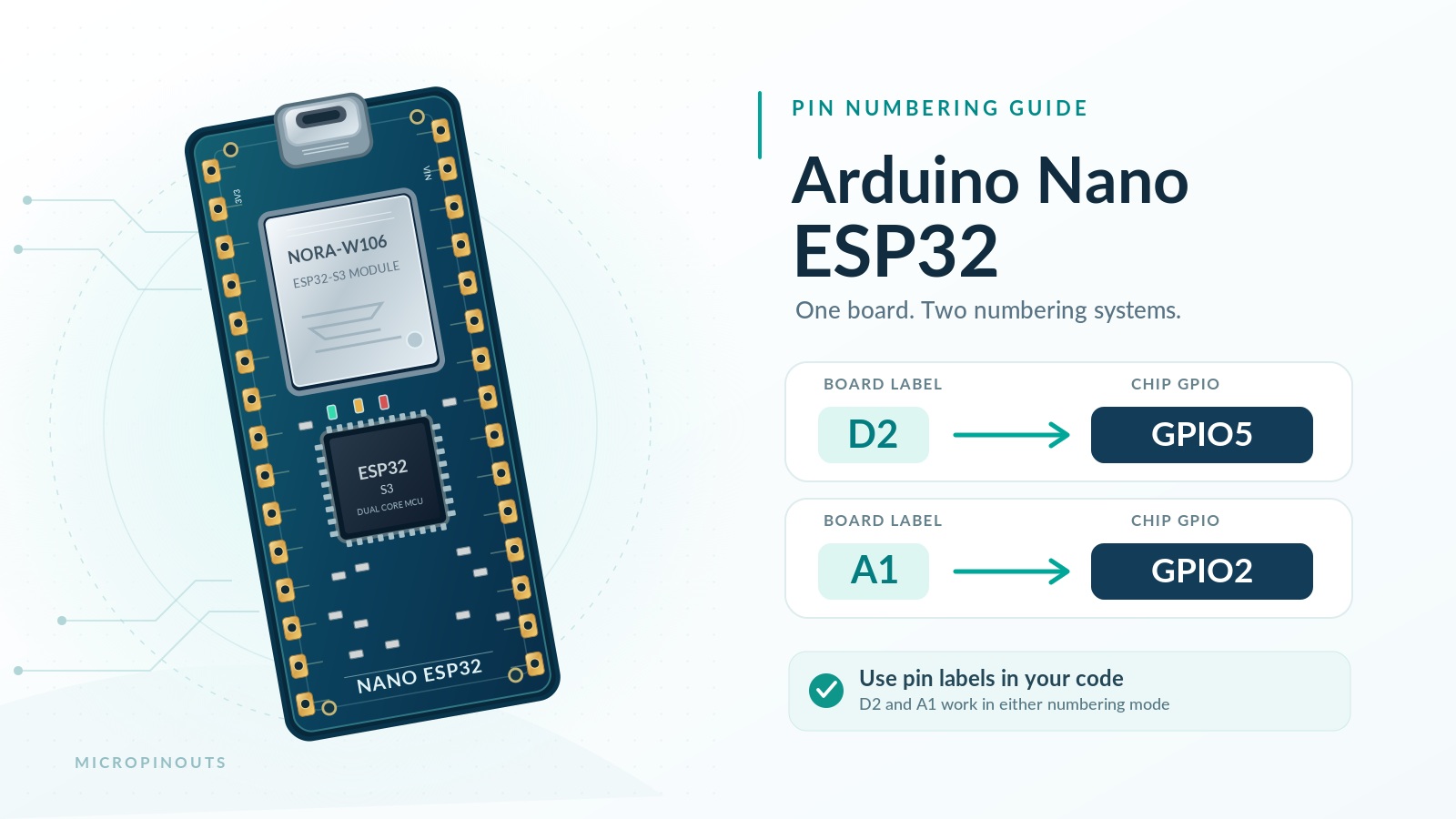
The Arduino Nano ESP32 has two sets of pin numbers. The board carries classic Nano labels such as D2 and A0, while the ESP32-S3 chip underneath uses its own GPIO numbers. The two sets do not match: the pin labelled...
The Arduino Nano ESP32 has two sets of pin numbers. The board carries classic Nano labels such as D2 and A0, while the ESP32-S3 chip underneath uses its own GPIO numbers. The two sets do not match: the pin labelled D2 is GPIO5, and GPIO2 is the pin labelled A1. Because of this, the number 2 in a sketch can address two different pins, depending on one setting in the Arduino IDE.
The fix is short: write the labels in your code. D2, A0 and the other labels always address the pin that carries that label, whichever setting is active. The rest of this guide gives the complete Arduino Nano ESP32 pinout map from D-labels to GPIO numbers, explains the two numbering modes, and shows which one to use with ESP32 libraries and MicroPython. The Arduino Nano ESP32 pinout page shows where each pin sits on the board.

Arduino Nano ESP32 D-Label to GPIO Map
The table below lists every labelled pin with both of its numbers. The Arduino pin number is the value the label has in the default mode, and the GPIO number is the one the ESP32-S3 uses.
Board label | Arduino pin number | ESP32-S3 GPIO | Default role |
|---|---|---|---|
D0 | 0 | GPIO44 | UART RX (Serial0) |
D1 | 1 | GPIO43 | UART TX (Serial0) |
D2 | 2 | GPIO5 | |
D3 | 3 | GPIO6 | |
D4 | 4 | GPIO7 | |
D5 | 5 | GPIO8 | |
D6 | 6 | GPIO9 | |
D7 | 7 | GPIO10 | |
D8 | 8 | GPIO17 | |
D9 | 9 | GPIO18 | |
D10 | 10 | GPIO21 | SPI chip select |
D11 | 11 | GPIO38 | SPI COPI |
D12 | 12 | GPIO47 | SPI CIPO |
D13 | 13 | GPIO48 | SPI SCK and onboard LED (LED_BUILTIN) |
A0 | 17 | GPIO1 | Analog input on ADC1 |
A1 | 18 | GPIO2 | Analog input on ADC1 |
A2 | 19 | GPIO3 | Analog input on ADC1 |
A3 | 20 | GPIO4 | Analog input on ADC1 |
A4 | 21 | GPIO11 | I2C SDA, analog input on ADC2 |
A5 | 22 | GPIO12 | I2C SCL, analog input on ADC2 |
A6 | 23 | GPIO13 | Analog input on ADC2 |
A7 | 24 | GPIO14 | Analog input on ADC2 |
LED_RED | 14 | GPIO46 | Red channel of the RGB LED, also header pin B0 |
LED_GREEN | 15 | GPIO0 | Green channel of the RGB LED, also header pin B1 |
LED_BLUE | 16 | GPIO45 | Blue channel of the RGB LED |
Two details in the table need a comment. The Arduino pin numbers for A0 to A7 start at 17, because 14, 15 and 16 belong to the three channels of the onboard RGB LED. The header pins B0 and B1 have no D-label. They are the chip's boot pins on GPIO46 and GPIO0, the same GPIOs that drive the red and green LED channels, so leave both unconnected in a project.
Why the Same Number Can Mean Two Pins
The mismatch comes from a design choice. Arduino numbered the pins to match the Nano form factor, so that projects made for other Nano boards keep working on the Nano ESP32. Code written for other ESP32 boards expects GPIO numbers. To serve both groups, the Arduino IDE offers two modes under Tools > Pin Numbering:
By Arduino pin (default). A bare number is an Arduino pin number, the standard for Nano boards.
By GPIO number (legacy). A bare number is a GPIO number, the standard for most ESP32 boards.
Take the line pinMode(2, OUTPUT). In the default mode it configures the pin labelled D2, which is GPIO5. In legacy mode the same line configures GPIO2, which is the pin labelled A1. The sketch compiles in both cases, so nothing warns you that the output moved to another pin.
The labels remove this ambiguity. The board package defines D2 as 2 in the default mode and as 5 in legacy mode, so pinMode(D2, OUTPUT) reaches the pin labelled D2 in both. The three lines below show the difference.
pinMode(D2, OUTPUT); // pin D2 in both modes pinMode(2, OUTPUT); // pin D2 only in By Arduino pin (default) pinMode(5, OUTPUT); // pin D2 only in By GPIO number (legacy) |
A change of mode takes effect with the next upload. To check which mode a sketch was compiled in, print the value of two labels:
void setup() { Serial.begin(115200); delay(2000); Serial.print("D2 = "); Serial.println(D2); Serial.print("A0 = "); Serial.println(A0); } void loop() { } |
In the default mode the sketch prints D2 = 2 and A0 = 17. In legacy mode it prints D2 = 5 and A0 = 1.
When to Switch to GPIO Numbering
The default mode works for the Arduino functions, such as digitalWrite() and analogRead(). Third-party ESP32 libraries are the exception. Arduino names OneWire, FastLED and ESP32Servo as libraries that do not support the pin numbers printed on the board and need the GPIO number.
Suppose a sketch in the default mode passes D6 to one of these libraries. D6 equals 6 in that mode, the library sends 6 to the chip as a GPIO number, and the signal appears on GPIO6, which is the pin labelled D3.
Arduino's answer is to select By GPIO number (legacy) whenever a sketch uses third-party ESP32 libraries. Keep the labels in your code after the switch. In legacy mode D6 equals 9, so the Arduino functions and the library both reach GPIO9, the pin labelled D6.
MicroPython follows the ESP32 convention as well. Its Pin() function takes GPIO numbers, so the LED on D13 is Pin(48), and Pin(11) addresses the pin labelled A4.
The same translation applies when you copy a sketch from a generic ESP32 tutorial. Its bare numbers are GPIO numbers, so either compile the sketch in legacy mode or replace each number with the label of the pin you wired. The table below summarizes all four situations.
Situation | What to write |
|---|---|
Arduino functions such as digitalWrite() and analogRead() | D and A labels, in either mode |
Third-party ESP32 library | Select By GPIO number (legacy) and keep the labels |
MicroPython | GPIO numbers from the map above |
Sketch copied from a generic ESP32 tutorial | Compile in legacy mode, or replace each number with a label |
Pins That Share a Function
Numbering is the main trap on this board. A few pins add smaller ones, because each of them does two jobs:
D13 carries the onboard LED (LED_BUILTIN) and the SPI clock, so the LED flickers during SPI transfers.
D0 and D1 are the header UART. In a sketch they belong to Serial0, while Serial is the USB port.
A4 and A5 are the default I2C pins. A second bus on Wire1 can use any free pair of pins, for example Wire1.begin(D4, D5).
A4 to A7 use ADC2, which Wi-Fi also uses, so readings on these pins can fail while Wi-Fi runs. A0 to A3 use ADC1 and are the analog inputs to choose in a Wi-Fi project.
The RGB LED is active-low. Writing LOW to LED_RED, LED_GREEN or LED_BLUE turns that color on. On some boards from the first production batch, the green and blue pins are swapped.
Every D and A pin supports analogWrite(), but the board can generate only five PWM signals at the same time.
Troubleshooting
The table below maps each symptom from this guide to its cause and fix.
Symptom | Cause | Fix |
|---|---|---|
A different pin switches than the one you wired | The sketch uses a bare number in the other numbering mode | Replace the number with the D or A label |
A third-party ESP32 library has no effect on its pin | The library treats the pin number as a GPIO number | Select Tools > Pin Numbering > By GPIO number (legacy) and upload again |
No data on D0 and D1 | The sketch uses Serial, which is the USB port | Use Serial0 |
Analog readings fail after Wi-Fi connects | The pin is on ADC2 (A4 to A7) | Move the signal to A0, A1, A2 or A3 |
An RGB LED color lights when you write HIGH to turn it off | The RGB LED is active-low | Write LOW to turn a color on and HIGH to turn it off |
Green and blue are swapped on the RGB LED | Some first-batch boards carry a different RGB LED |
Conclusion
The Arduino Nano ESP32 has two numbering schemes, and the labels printed on the board work in both. Write D2 and A0 in place of bare numbers, switch to By GPIO number (legacy) when a sketch uses a third-party ESP32 library, and use the GPIO column of the map for MicroPython. For pin positions and the complete function list, see the Arduino Nano ESP32 pinout page.
Sources
Select pin numbering for Nano ESP32 in Arduino IDE (Arduino Help Center)
Nano ESP32 Selecting Pin Configuration (Arduino)
Arduino Nano ESP32 Cheat Sheet (Arduino)
pins_arduino.h for the Arduino Nano ESP32 (Espressif)
Blink a led on a breadboard with Micropython and Arduino ESP32 (Arduino Forum)