3.3V vs 5V Logic: Can I Connect These Boards Together?
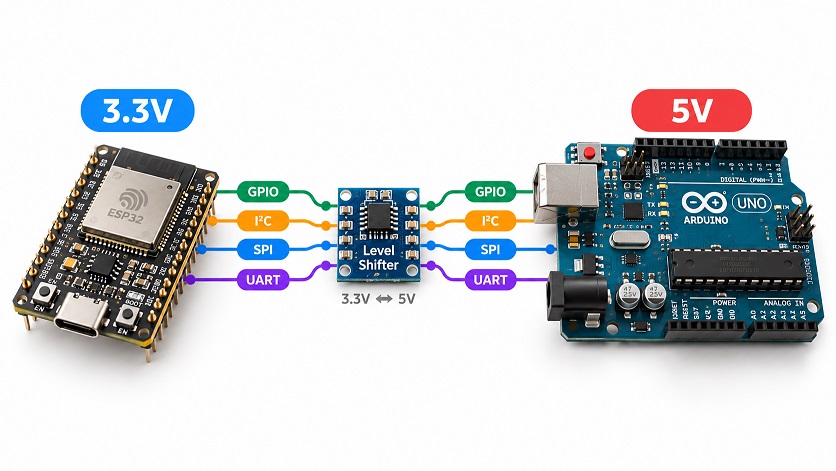
You have a 3.3V microcontroller board and a 5V sensor, display or module. Can you connect them directly? Sometimes. But simply seeing 3.3V printed on one board and 5V printed on another does not tell you enough to...
You have a 3.3V microcontroller board and a 5V sensor, display or module, and you want to know whether you can connect them directly. Sometimes you can. The 3.3V and 5V printed on the boards do not tell you enough to wire them together safely, because those labels can refer to three different things: the power-supply voltage, the GPIO logic voltage, and the maximum voltage a GPIO can tolerate. Confusing these values is an easy way to damage a microcontroller.
This guide explains how 3.3V and 5V logic work, when you can connect two devices directly, and when you need a voltage divider or a logic-level converter.
Power Voltage and Logic Voltage Are Not the Same Thing
Many development boards take 5V power from USB even though the microcontroller on them uses 3.3V logic. The voltage that powers a board, in other words, is not necessarily the voltage on its GPIO pins.
The Raspberry Pi Pico is a good example. Its power circuitry accepts a VSYS supply from approximately 1.8V to 5.5V, yet its digital GPIO pins operate at around 3.3V. Many ESP32 development boards follow the same pattern. You can supply them from USB or a 5V/VIN pin, while the ESP32 itself runs from the nominal 3.3V supply that Espressif recommends for the chip and module.
This is why the following reasoning is dangerous: "The board has a 5V pin, therefore its GPIO pins accept 5V." A board's power input and its GPIO limits are two separate specifications.
What Does 3.3V Logic Mean?
A digital signal has two states: LOW, which represents logic 0, and HIGH, which represents logic 1. A 3.3V microcontroller drives a HIGH signal close to 3.3V, and a 5V microcontroller drives it closer to 5V.
A problem occurs when the output voltage of one device exceeds what the receiving device can safely accept. If the TX pin of a 5V MCU drives the RX pin of a 3.3V MCU, the 3.3V input sees approximately 5V. Unless that input is specifically rated as 5V tolerant, the connection can exceed its electrical limits.
The opposite direction raises a different question. When a 3.3V TX pin drives a 5V RX pin, the 5V device is not exposed to excessive voltage. What matters there is whether 3.3V is high enough for the 5V input to recognize as HIGH. The next two sections cover these two compatibility problems, starting with the HIGH threshold.
Logic HIGH Does Not Have to Equal the Supply Voltage
Digital inputs do not switch at exactly 3.3V or exactly 5V. The datasheet defines two voltage thresholds instead. VIH is the minimum input voltage that is guaranteed to read as HIGH, and VIL is the maximum input voltage that is guaranteed to read as LOW.
Suppose a 5V device specifies a VIH of 3.0V. A 3.3V GPIO output can normally meet that requirement. Another 5V device might require a higher input voltage, however, so you cannot assume that every 3.3V output will reliably drive every 5V input.
Arduino Uno Example
The ATmega328P on the classic Arduino Uno runs at 5V. For ordinary digital inputs, its specification gives a minimum HIGH input level of 0.6 × VCC when the chip operates above 2.4V. At 5V, that gives:
VIH(min) = 0.6 × 5V = 3.0V
A nominal 3.3V digital output therefore meets the HIGH threshold of a 5V ATmega328P input. This is why you should judge voltage compatibility from the input threshold specification and not from the 3.3V and 5V labels alone. The result applies to this chip only, so do not assume it for every 5V microcontroller.
5V Into a 3.3V GPIO Is the More Dangerous Direction
Connecting a 5V output to a 3.3V input requires more caution, because the receiving GPIO has a maximum permitted input voltage. Exceeding it can forward-bias internal protection structures, cause unreliable operation or permanently damage the device.
For ESP chips, Espressif states that the GPIO voltage tolerance is 3.6V and recommends a voltage divider when a signal exceeds that value. A standard 5V digital signal should therefore not connect directly to a normal ESP32 GPIO. The same rule applies to any microcontroller: never assume a 3.3V GPIO is 5V tolerant unless the manufacturer's documentation explicitly says it is.
What Does "5V Tolerant" Mean?
Some 3.3V microcontrollers have digital input pins that are designed to accept 5V signals without damage. These pins are called 5V tolerant, and the rating can come with several restrictions. A pin may be 5V tolerant only:
When configured as a digital input
When the MCU is powered
On certain GPIOs
When analog mode is disabled
Within particular current or voltage conditions
Because of these restrictions, a forum post that calls a chip "5V tolerant" is not enough. Check the datasheet for the specific MCU and the specific pin. Remember also that a 5V-tolerant pin does not output 5V. A 3.3V MCU with 5V-tolerant inputs will generally still drive a HIGH of approximately 3.3V.
A 5V Power Pin Does Not Make GPIO 5V Tolerant
Many wiring mistakes come from reading a power pin's label as a GPIO rating. Development boards frequently expose pins labeled 5V, VBUS, VIN or VSYS. These are generally power connections, and they do not describe the electrical limits of the GPIO pins beside them.
The two boards from the first section show this. The Raspberry Pi Pico exposes VBUS and VSYS power connections, while its RP2040 circuitry uses nominal 3.3V I/O supplies. An ESP32 development board can have a 5V input or USB supply, while its GPIOs remain subject to the 3.6V tolerance that Espressif specifies. Always look for a board's logic voltage or GPIO electrical specification separately from its power-input specification.
When Do You Need a Logic-Level Converter?
A level shifter, also called a logic-level converter, translates signals between voltage domains, for example from 5V logic to 3.3V logic. Consider one in any of these cases:
A 5V output drives a 3.3V GPIO that is not 5V tolerant
A 3.3V output cannot meet the receiving device's HIGH threshold
Signals travel in both directions
Multiple signal lines require conversion
The interface runs at relatively high speed
You want a design that does not rely on borderline thresholds
Different protocols also need different types of level shifting, which the sections on I2C, UART and SPI cover. Before those, the next section looks at the simplest option, a voltage divider.
Using a Voltage Divider
For a signal that travels in one direction, a resistor divider can reduce 5V to a safer level. R1 connects between the 5V signal and the input, and R2 connects between the input and ground. The voltage at the input is then:
Vout = Vin × R2 / (R1 + R2)
With R1 at approximately 10k ohms and R2 at approximately 20k ohms, a 5V signal becomes 5 × 20 / 30, or approximately 3.33V.
This works well for relatively slow, unidirectional digital signals, but a resistor divider is not a universal level shifter. It cannot actively translate a signal in both directions, which makes it unsuitable as a general solution for bidirectional buses such as I2C. It can also affect signal edges at higher speeds, because the resistance interacts with the input and wiring capacitance.
I2C Needs Special Attention
I2C works differently from normal push-pull GPIO signals. SDA and SCL are normally open-drain signals: devices pull a line LOW, and pull-up resistors connected to the bus supply produce the HIGH state. The I2C specification defines these pull-ups as part of the bus electrical architecture, so the voltage they connect to sets the HIGH level of the whole bus.
Imagine a 3.3V microcontroller connected to a 5V I2C sensor module. If the sensor breakout has SDA and SCL pull-ups connected to 5V, the bus rises toward 5V whenever no device pulls it LOW, and that can expose the 3.3V microcontroller inputs to 5V. Three solutions are possible:
Move the pull-ups to 3.3V, if every device accepts 3.3V as HIGH
Remove the conflicting onboard pull-ups
Use a bidirectional I2C level shifter
A common I2C level translator uses MOSFETs so that both voltage domains can pull the same bus LOW while each side keeps its own HIGH voltage. Before you connect a module sold as a "5V I2C module," check its supply voltage and also where its SDA and SCL pull-up resistors connect.
UART Voltage Compatibility
UART is generally simpler, because TX and RX are separate signals that each travel in one direction. Suppose you connect a 5V Arduino to a 3.3V ESP32. Arduino TX drives ESP32 RX, and ESP32 TX drives Arduino RX.
The first of these lines needs protection. The Arduino TX signal may approach 5V, and the ESP32 GPIO should not receive that directly, because Espressif specifies a GPIO tolerance of 3.6V. Use a divider or a level shifter between Arduino TX and ESP32 RX.
The second line may not need conversion if the 5V device reliably recognizes 3.3V as HIGH. The ATmega328P does: its specified HIGH threshold at a 5V supply is 3.0V, so a nominal 3.3V signal meets it. Other 5V devices may have a higher threshold, so check the receiving device first.
TTL UART Is Not RS-232
The UART peripheral on a microcontroller usually uses logic-level voltages such as 3.3V or 5V. Traditional RS-232 is electrically different, so do not connect an RS-232 connector directly to the RX and TX pins of an MCU. Use an RS-232 transceiver between the two voltage domains.
SPI Can Have Mixed Directions
SPI commonly uses four signals: MOSI, MISO, SCK and CS. When a 5V MCU communicates with a 3.3V SPI peripheral, MOSI, SCK and CS travel from the 5V side toward the 3.3V device, so all three may require level shifting. MISO normally travels the other way, from the 3.3V peripheral to the 5V MCU. That line may work directly if the MCU's input HIGH threshold is low enough, which its datasheet will confirm.
SPI can also operate at much higher frequencies than UART or typical I2C buses, so a resistor divider that appears fine at low speed may degrade fast edges. For high-speed SPI, use a level translator designed for the required frequency.
Analog Inputs Are Different Again
Do not assume that digital 5V tolerance also applies to ADC inputs. Analog pins are constrained by the ADC's allowable input range. On a board with a 3.3V ADC reference, a 5V analog signal can exceed that range even if some of the microcontroller's digital pins are described as 5V tolerant.
To measure a 5V analog signal with a 3.3V ADC, you can scale it down with a properly designed resistor divider, so that a 0 to 5V signal fits the 0 to 3.3V ADC range. Choose resistor values that also meet the ADC's source-impedance requirements.
Grounds Must Normally Be Connected
Voltage compatibility is not the only requirement when you connect two boards. They also need a common reference voltage, so for most directly connected digital interfaces you connect the ground of one board to the ground of the other. Without a common ground, the voltage at a GPIO has no reliable reference between the two circuits. This applies to I2C, SPI, UART and most ordinary GPIO connections.
Intentionally isolated interfaces are the exception. Those designs use isolation components to transfer signals without sharing ground.
Module Supply Voltage Can Be Misleading
Breakout boards make voltage compatibility especially confusing. A module advertised as "3.3V-5V compatible" might include any of the following:
A voltage regulator
A logic-level converter
Series resistors
5V-tolerant components
Or the label might mean only that the module's main IC operates over a broad supply range. These situations are not electrically equivalent. For example, a breakout board may accept 5V on its VCC pin because it contains a 3.3V regulator, while its signal pins still connect directly to a 3.3V sensor IC. Check the breakout board's schematic whenever possible.
A Quick Compatibility Checklist
Before you connect two boards, answer these eight questions.
What voltage powers each device? Check the acceptable supply range, and do not confuse it with the GPIO voltage.
What is the GPIO logic voltage? Determine whether each side uses 1.8V, 3.3V, 5V or another logic level.
What is the maximum GPIO input voltage? If one device outputs more than the receiving GPIO permits, level shifting is required.
What is VIH? When a lower-voltage device drives a higher-voltage input, its HIGH output must exceed the receiving device's guaranteed HIGH threshold.
Which direction does each signal travel? UART TX and RX travel in opposite directions, SPI has signals traveling both ways, and I2C is bidirectional. The level-shifting method depends on the direction.
Are there pull-up resistors? This is particularly important for I2C. Determine which voltage the pull-ups connect to.
Is the pin analog or digital? Do not assume that a digital pin's voltage tolerance applies to the ADC.
Do both boards share ground? For ordinary non-isolated interfaces, they normally should.
Common 3.3V and 5V Connection Cases
The table below gives the typical result for each type of connection and what to check.
Connection | Typical Result | What to Check |
|---|---|---|
3.3V output -> 3.3V input | Usually direct | Pin limits |
5V output -> 5V input | Usually direct | Pin limits |
3.3V output -> 5V input | Sometimes direct | VIH of 5V input |
5V output -> 3.3V input | Often unsafe | 5V tolerance or level shift |
3.3V I2C -> 5V I2C | Needs investigation | Pull-up voltage and VIH |
5V analog -> 3.3V ADC | Usually needs scaling | ADC input range |
Use these results as starting points, because the datasheets determine the real answer.
Can I Connect These Boards Together?
Knowing that one board is "a 3.3V board" and the other is "a 5V board" does not settle whether they are compatible. Check four separate properties: supply voltage, logic voltage, maximum GPIO input voltage and logic HIGH threshold.
Then look at how the interface works. A UART connection may require level shifting in only one direction, and SPI may require it on several signals. I2C may require a bidirectional level shifter or only the correct pull-up voltage, and analog inputs need to stay within their ADC range. Once you know these properties, it becomes much easier to determine whether two boards can be connected safely.
MicroPinouts board pages list supply voltages, logic voltages and individual pin functions, which makes these checks easier before you start wiring a circuit.